The slab meshing is treated similar to analysis results. When the results of an analysis are deleted, the slab mesh is cleared to be re-built during the next solution. When a solution results file is saved, the meshed elements will be included in that file.
Note:
The global mesh size for the slab can be input on the Solution tab of the Model Settings. As a smaller mesh size is more accurate, the mesh size can get too small. The smaller mesh size will lead to longer solution time and more memory usage.
By default, the plate elements associated with the slab are not visible to the user. The mesh can be turned on using the setting on the Model Display Options - Slabs tab. Listed under the Wireframe selection, the Outline Plates check box will turn the display of the slab mesh on or off.
Note
Point constraints are the locations within the slab that require connectivity to the meshed plate elements. The program will automatically generate point constraints at the following locations:
1. Support points which include: joints along a wall panel and column joints (see Column Meshing for full description).
2. Beams points which include: the start, end and intermediate joints along the beam.
3. Column shear cap extents.
Note:
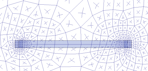
Beams drawn on a Two-Way slab are meshed directly to the surrounding plates. The picture below shows the center-line of the beam is meshed to the plates.
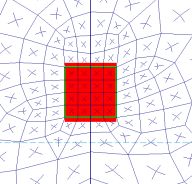
The top of the column will be submeshed and connected to the surrounding plates with rigid links in a 12" x 12" square. This approach is more accurate than modeling the column connection at only one node. When only one node is used the slab will have a higher peak moment and higher deflection at that one point. Instead the rigid links create a rigid region over the top of the column that approximate the stiffness of the column attachment to the slab. The size of the rigid links will not change based on the column dimensions as this is only approximate. In most cases there will be 4 plates inside the rigid links.
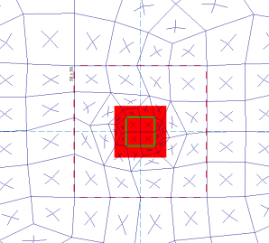
The column node will connect to the slab via the additional diagonal rigid links. After the slab is meshed, additional diagonal rigid links are drawn to connect the column node to the square rigid links (shown below). The column node has rotational and translational support so there will be vertical and rotational constraint at the column location.

In most cases, the column node will land inside the 2x2 plate mesh in the same location as a plate corner. However, in certain edge and corner situations, as well as beam intersections, the column node will not align with the plate corners.

|
|
| Edge Column | Beam Intersecting a Column |
Note:
The slab connection to the column rigid link top depends on the model merge tolerance being within the 12"x12" rigid link square. If the model's merge tolerance has been set too high in the Model Settings, the slab mesh may not connect to the columns as seen by the deflected shape and slab forces. If this occurs, reduce the merge tolerance back to the default 0.12" and the slab mesh will attach to the column.
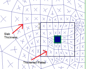
Shear caps can be added to columns. See the Shear Cap Considerations section to learn more about how to model Shear Caps. The Shear Cap will automatically thicken the plates in the area designated by the shear cap. For example, the Shear Cap shown below as 60"x60" will have thicker plates (the sum of the regular slab depth and the depth of the shear cap). The Shear Cap will alter the analytical force distribution by thickening the plates in this area.
Aside from the Strength considerations mentioned above (Flexure and Shear), Elevated Slabs must be checked for Serviceability (i.e. Deflection). RISAFloor ES checks deflection on slabs in three ways:
ACI 318-14 Section 8.3.1.1 (ACI 318-11 Section 9.5.3.2) specifies a minimum permissible slab thickness as a function of clear span between supports. RISAFloor ES checks this value using Span Length and Support Dimensions and produces a warning if these requirements are not met.
ACI 318-14 Section 24.2.2 (ACI 318-11 Section 9.5.2.6) specifies a maximum permissible deflection as a function of span between supports. RISAFloor ES calculates a deflection for each Span based on FEA and checks this value using Span Length. A warning is produced if these deflection requirements are not met. The default Slab Design Rules conform to the requirements of ACI 318-14 Table 24.2.2 (ACI 318-11 Table 9.5b), however you may manually override these Design Rules to impose other deflection criteria. See the Elevated Slabs - Spreadsheet Results topic for more information.
There is no ACI requirement regarding absolute deflection, however absolute deflections of the slab may be important for design considerations specific to your building. RISAFloor ES calculates the absolute deflection at many locations in the slab and reports those in the Slab Point Deflections spreadsheet. Because there is no way to specify deflection limits for absolute deflection, no checks or warnings are produced. See the Elevated Slabs - Spreadsheet Results topic for more information.
The Slab Point Deflections are calculated using finite element analysis. The program runs deflection analysis for all of the Service Load Combinations (those with the Service Checkbox turned on). Deflections are reported for all Points within a slab. Points are typically located at the corners of the plate elements which comprise the slab mesh.
To view the point deflections results, see the Slab Point Deflections spreadsheet.
Note:
Selecting a Deflection Method of I Cracked/Elastic in the Model Settings controls the stiffness reduction based on the Icr factor in the Slabs spreadsheet .

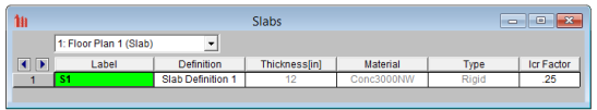
The Icr factor default is set to 0.25 per ACI 318-14 Section 6.6.3.1.1 (ACI 318-11 Section 10.10.4.1). You can modify this factor with any value between zero and 1.0 by typing in this field. The Icr factor adjusts the stiffness of the plate elements comprising the slab by altering the thickness during solution. This adjusted thickness does not, however, affect design values (reinforcement calculations).
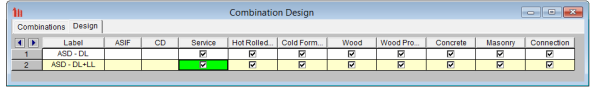
The Service checkbox in Load Combinations- Design tab currently only applies to Concrete Floor Slabs in RISAFloor ES.
The commentary in ACI 318-14 Section 6.6.3.2.2 (ACI 318-11 Section 10.10.4.1) recommends a 1.43 factor to be applied to the cracked moment of inertia for all service loads. The program applies this factor to all Load Combinations that have the Service checkbox turned on, as long as the Use Cracked Slabs is selected in the Model Settings. This results in an effective default slab moment of inertia of (0.25)*(1.43)*Ig = 0.3575*Ig
Note: The Long Term Deflection will also give the cracking analysis for the Service Load Combinations in the graphical display, spreadsheet results and Detail Report.
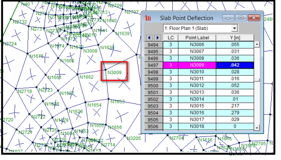
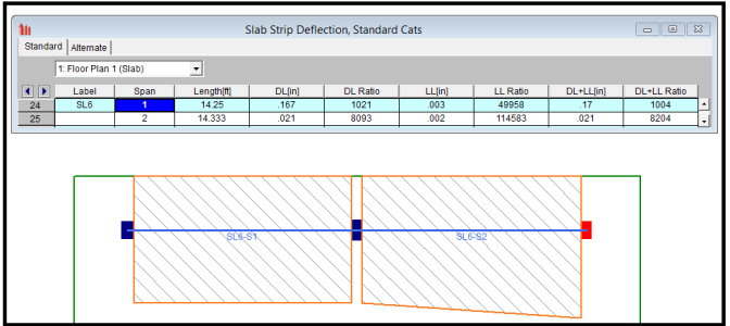
The Slab Point Deflections are the absolute deflections of every point inside the plate mesh based on the Load Combination. The Design Strip Deflections are the deflections within the Design Strip based on each Load Category. These are both very useful in different ways. The Point Deflections can help you identify exact low points in a slab. The Design Strip Deflection is closer to building code requirements because it helps you check the deflection ratio within a span.
Slab Point Deflection example:
Slab Strip Deflection Example:
Long Term Deflection is available for Concrete Floor Slabs using Design Method: User Defined.
With Long Term Deflection turned on, the program will automatically adjust the plate stiffness by adjusting the Moment of Inertia to be Ie (ACI-14 24.2.3.5). This stiffness adjustment is an iterative analysis per plate based on the global axis.
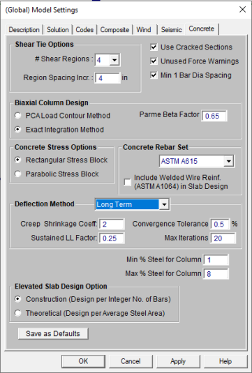
Turn on the Long Term Deflection analysis in the Model Settings- Concrete tab.
Creep Shrinkage Coeff:Multiplier used for additional deflection due to long-term effects. This coefficient is described as lD for further information refer to ACI-14 24.2.4.
Sustained LL Factor:There are internal Load Combinations included when the Long Term Deflection analysis is turned on. The Sustained LL Factor gets used in the Load Combination listed below.
Sustained Load: DL + (Sustained LL Factor)*LL
Long Term Sustained: Sustained Load * (1 + Creep Shrinkage Coeff)
Total Load: DL + LL
Long Term: Long Term Sustained + ( Total Load - Sustained Load )
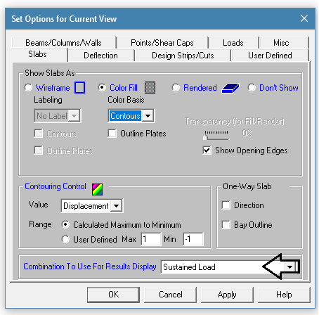
These internal Load Combinations can be shown in the Slab-Contours- Displacements as well as the Slab Point Deflections.
Convergence Tolerance:The long term deflection is an iterative analysis to find the Effective Moment of Inertia, Ie. This tolerance is used to set how close a subsequent solution must be to the previous solution to be considered converged.
Max Iterations: This is the maximum number of analytical iterations the program will go before it stops.
Note: When Long Term Deflection is turned on, the program will NOT use simplified methods for Cracked Slabs (Icr) when calculating deflections for these internal load combinations listed above. The simplified method using Icr factor is still used in the user defined load combinations in the Load Combinations spreadsheet.
The Long Term Deflection can be viewed graphically using the Slab Contours-Displacement. The internal Load Combinations are listed in the Plot Options.
There is also an icon that can be added to quickly display all the graphical views of displacement.
The Slab Point Deflection spreadsheet will show the node displacement per each internal load combination.

Notes and Limitations: